Example - AIR - AIR heat exchanger
|
Type |
without shell compensator |
|
|
Floor panels |
||
|
Type of base plate |
Program specification |
|
|
in section 1: |
||
|
Storage |
fixed |
|
|
Thickness |
44 mm |
|
|
in section M: |
||
|
Storage |
fixed |
|
|
Thickness |
44 mm |
|
|
Coat |
||
|
Cross section |
circular |
|
|
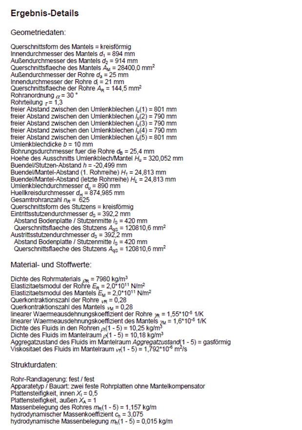
Inner diameter d1 |
894 mm |
|
|
Outer diameter d2 |
914 mm |
|
|
Tubes |
||
|
Outer diameter da |
25 mm |
|
|
Inner diameter di |
21 mm |
|
|
Total length lR |
4100 mm |
|
|
Socket |
||
|
Cross section |
circular |
|
|
Entry spigot |
||
|
Clearance between the center of the entry spigot and the first base plate lS |
420 mm |
|
|
Inner diameter dS |
392,2 mm |
|
|
Outlet nozzle |
||
|
Clearance from nozzle center to base plate lS |
420 mm |
|
|
Inner diameter dS |
392,2 mm |
|
|
Position of the outlet nozzle |
below |
|
|
Baffles |
||
|
Diameter dU |
890 mm |
|
|
Number nU |
4 |
|
|
Thickness b |
10 mm |
|
|
Height of the cutout baffle / jacket HU |
320,05 mm |
|
|
or d u.x |
35,8 % |
|
|
Distances between the baffles |
||
|
lU(1) |
806 mm |
|
|
lU(2) |
800 mm |
|
|
lU(3) |
800 mm |
|
|
lU(4) |
800 mm |
|
|
lU(5) |
806 mm |
|
|
Bore diameter for the tubes |
25,4 mm |
|
|
Coat |
||
|
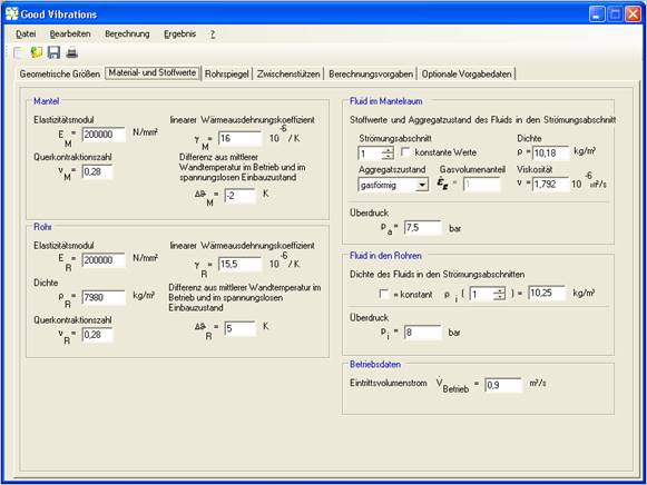
Modulus of elasticity EM |
20000 N/mm² |
|
|
linear coefficient of thermal expansiongM |
16 10 -6/K |
|
|
Transverse contraction coefficient |
0,28 |
|
|
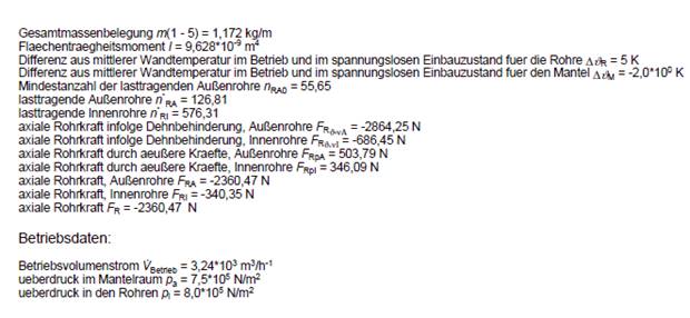
Difference between mean wall temperature in operation and in the de-energized installation state |
-2 K |
|
|
Tubes |
||
|
Modulus of elasticity ER |
20000 N/mm² |
|
|
linear coefficient of thermal expansion gR |
15,5 10 -6/K |
|
|
Density rR |
7980 kg/m³ |
|
|
Transverse contraction coefficient |
0,28 |
|
|
Difference between mean wall temperature in operation and in the de-energized installation state |
5 K |
|
|
Fluid in jacket space |
||
|
Flow sections 1 - 5 |
constant |
|
|
Density r |
10.18 kg/m³ |
|
|
Aggregate state |
gaseous |
|
|
Gas volume fraction |
1 |
|
|
Viscosity |
1.792 10 -6 m²/s |
|
|
Overpressure pa |
7,5 bar |
|
|
Fluid in jacket space |
||
|
Flow sections 1 - 5 |
constant |
|
|
Density r |
10.25 kg/m³ |
|
|
Overpressure pi |
8 bar |
|
|
Operating data |
||
|
Inlet volume flow |
0.9 m³/s |
|
|
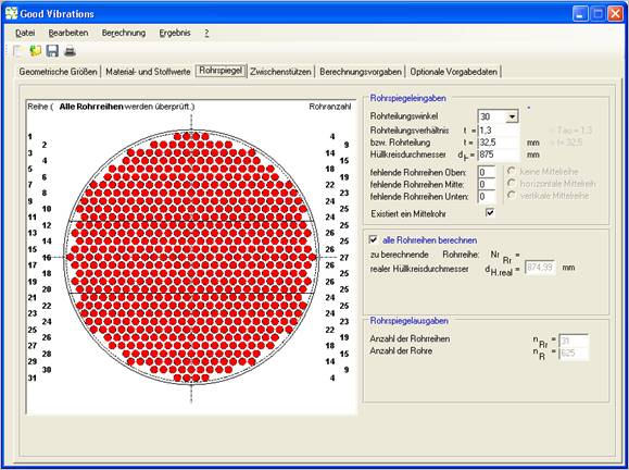
Pipe mirror input |
||
|
Pipe pitch angle |
30° |
|
|
Pipe pitch ratio t |
1,3 |
|
|
or pipe pitch |
32,5 mm |
|
|
Enveloping circle diameter |
875 mm |
|
|
missing pipe rows above |
0 |
|
|
missing pipe rows center |
0 |
|
|
missing pipe rows below |
0 |
|
|
exists a center tube |
ticked |
|
|
Calculate all pipe rows |
ticked |
|
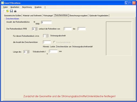
No support grids or partial support grids were provided.
|
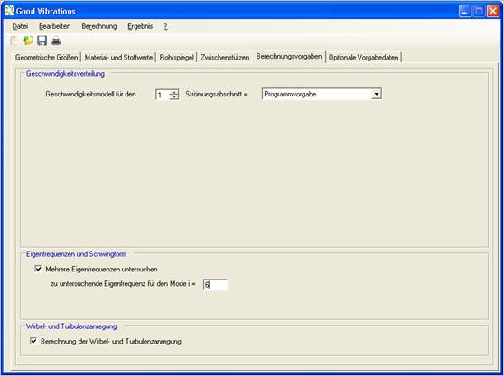
Speed distribution |
||
|
Velocity model for all flow sections |
Program specification |
|
|
Natural frequency and mode of vibration |
||
|
Examine multiple natural frequencies |
ticked |
|
|
Natural frequency to be investigated for mode i |
6 |
|
|
Vortex and turbulence excitation |
||
|
Calculation of vortex and turbulence excitation |
ticked |
|
No optional defaults selected.
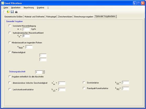
Start the calculation by selecting the "Calculation / Start" menu (CTRL-R)
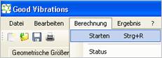
Start the calculation by selecting the "Calculation / Start" menu (CTRL-R)
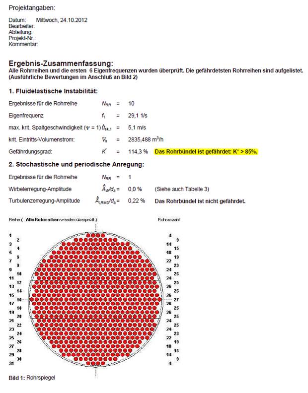
A new window will open with the results, the first page contains a summary.

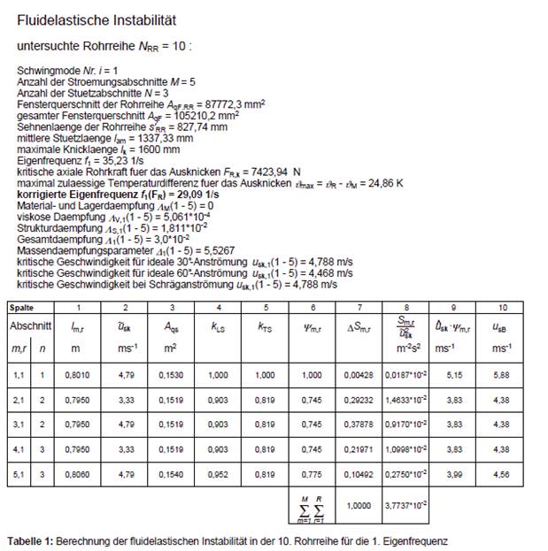
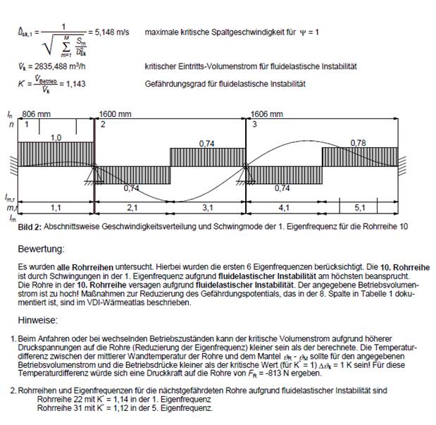
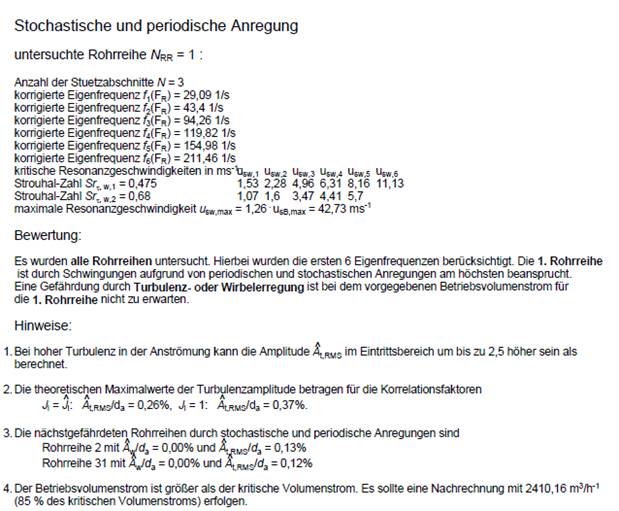
For interpretation of the results, see output descriptions . In this example, the bundle is at risk of vibration due to fluid elastic instability. Degree of hazard 114.3 %.