General product description
The GOOD VIBRATIONS program is used to design and check shell-and-tube heat exchangers with the 4 standard tube arrangements (30°, 45°, 60° and 90°) with regard to the prevention of short-term damage due to flow-induced vibrations in the bundle caused by fluid-elastic instability or vortex excitation during cross-flow. The maximum amplitudes due to vortex and turbulence excitation are also calculated to estimate the service lives due to long-term damage.
The calculations are based on the design guidelines of the VDI Heat Atlas, Chap.Oc, 9th edition 2002 and 10th edition 2006 [1], which contain significant improvements compared to the 8th edition 1997. The program enables the user to design heat exchangers with the four standard tube arrangements according to the basic equations of the heat atlas not only more accurately and for more complex tube support conditions, but also provides variant calculations in the shortest possible time.
The structural data of the tubes can also be calculated with variable mass occupancies and material data. For the calculation of the natural frequencies and the natural mode shapes, an analytical solution algorithm for straight tubes was implemented in the main routine. The critical velocities for gas and liquid flows in ideal bundles and with homogeneous distribution are calculated using the stability diagrams in the VDI Heat Atlas [1,2].
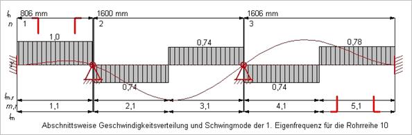
The great advantage of the program is the consideration of the real velocity distribution and of variable material and structure data along the heat exchanger axis. This is possible due to the implementation of analytical models for the approximate calculation of the velocity distribution depending on the position and the upstream flow conditions of the tubes. The critical velocities are also calculated section by section for each row of tubes, taking into account any oblique flow and the degree of risk to the tubes from the edge gap shell/bundle [3,4].
Other velocity distributions and critical velocities, e.g. for two-phase flows, can optionally be freely specified for each section. An increased hazard of edge pipes at vertical center aisles without displacement bodies due to the aisle velocity is not recorded. If no specifications are made, e.g. for the pipe row to be calculated or for one or more oscillating shapes, the program calculates by default all pipe rows in the bundle for the first 6 specific modes.
The GOOD VIBRATIONS program has a menu-guided interface that can be used to enter all the necessary geometric quantities, stock, material and operating data, as well as optional values for designs deviating from the standard, quantity flows, stock values or speeds.
The pipe level is created automatically. The standard pipe surface can be approximated to the actual one by removing or shifting pipe rows, whereby vertical alleys are not taken into account. These are to be closed by displacement bodies or baffles. The pipe rows to be calculated are highlighted in the cross-section.
All given data can be saved together with the project details (date, name, project number, comments).
The result is output for
·
The pipe series endangered by fluid-elastic
instability and the associated oscillating shape;
the next two endangered pipe series or specific modes are also listed.
· the pipe row endangered by vortex or turbulence excitation
· Calculation of velocity distributions in all flow sections of cross-flow apparatus (inlet, outlet and window sections)
· Calculation of all pipe rows in the bundle of cross-flow apparatus and the determination of the most vulnerable pipe row.
· Calculation of the vibration modes and frequencies by a fast analytical solution method
· Consideration of higher modes and corresponding natural frequencies, mode shapes, energy ratios, and Strouhal numbers.
· Consideration of the edge gap influence (shell/bundle) of the respective pipe series
· Determination of the vibration hazard due to turbulence and vortex excitation for all pipe rows of cross-flow apparatus and determination of the most vulnerable pipe row taking into account higher modes and specifying the maximum amplitudes, which are a direct measure of the degree of hazard. The axial velocity distribution is taken into account and the excitation forces are weighted by the vibration mode. In the case of vortex excitation, the resonance distance varying along the tube axis is also taken into account via the frequency ratio and the integral value of an amplitude amplification function.
Status 10-2012
Different spigot dimensions are provided for inlet and outlet spigots
For the normal case of pure cross flow, the program automatically determines the position of the outlet nozzle (top or bottom). For mixed cross- and longitudinal flow, the position of the outlet nozzle can be specified.
The size and position of the outlet nozzle influence the velocity distribution in the last three rows of pipes in the outlet area.
When the number of baffles is changed, the values for the three substance data (densities and viscosities in the shell space and in the pipes) are not deleted, but are set "constant" for all flow sections to the value of the first flow section.
Supporting points = supporting grids or partial supporting grids comprising only some rows of pipes
Flow section = section between the baffles or between the tube sheet and the baffle plate
Support plates can be specified in a new input sheet for several pipe row blocks, i.e. for RR x to RR y in each case, after calling up the pipe sheet, i.e. when the pipe row number and numbering are known. Each flow section, defined by the baffle spacing with length lU, can be divided into support sections with either constant spacing or by specifying the section lengths. The length of the last section with the highest index number is automatically calculated by the program from Σ lU,r = lU.
Support plates or support grids are not distinguished by the program when calculating the structural data. The program cannot automatically take into account the different influence of the flow through plates (cross flow) and through grids (axial flow); optional specifications of cross flow factors or velocity distributions are necessary for this. If the number of pipe rows and numbering are subsequently changed, the support data entered will not be reset if the pipe level (t, τ, α) is otherwise the same (warning message!).
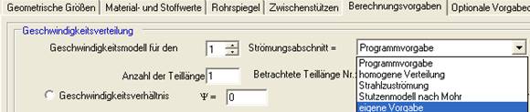
The input sheet "Calculation defaults" allows the selection of velocity distributions within a flow section, either as "Program default Homogeneous" or as "Own default".
The program calculates the flow length lm for each pipe row and flow section m and divides this into partial lengths lm,r if necessary. If support plates are installed, these partial lengths do not change. The cross-sectional constriction in a flow section is taken into account by reducing the flow area with the factor (lm - nSt - b) / lm - with nSt = number and b = width of the support plates.
a. Each flow section can be subdivided into partial lengths of lU with constant distances or by specifying the section lengths lUm,r, as when specifying the support distances. The length of the last partial section with the highest index number is automatically calculated by the program from
Σ lUm,r = lU.
When entering, the flow length lm is not yet known. It depends on the pipe series and the flow section. Therefore, the partial lengths lm,r are calculated by the program:
lm,r = lUm,r - lm / lU with Σ lm,r = lm.
If support plates are present, the part lengths do not change. Instead, the flow areas are reduced accordingly.
b. As an alternative to specifying the rel. velocity ratio ψ, it is possible to specify the flow fraction kS for each partial length r. It must be valid: Σ kS,r = 1.
The correction factors "Inflow factor kES" and "Edge gap factor kRS" can be preset with a constant value for all flow sections or any value can be entered for each flow section.