List of variables
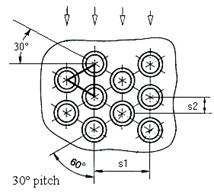
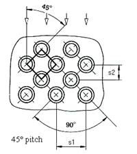
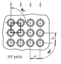
Distance of tube center to tube center of two adjacent tubes in one row
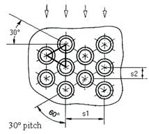
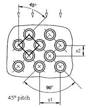
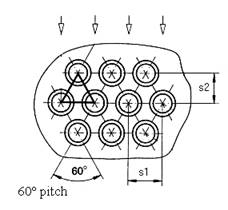
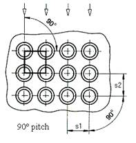
Distance between two tube rows in flow direction
|
Number of tube-side passes |
|||||
|
1 |
2 |
3 |
4 |
6 |
8 |
|
|
|
|
|
|
|
|
Type 0 |
Type 1 |
Type 10 |
Type 2 |
Type 4 |
Type 6 |
|
|
|
|
|
|
|
|
|
|
|
Type 3 |
Type 5 |
Type 7 |
|
|
|
|
|
|
|
|
|
|
|
Type 8 |
|
|


|
Number of tube-side passes |
|||||
|
1 |
2 |
3 |
4 |
6 |
8 |
|
|
|
|
|
|
|
|
Type 0 |
Type 1 |
Type 10 |
Type 2 |
Type 4 |
Type 6 |
|
|
|
|
|
|
|
|
|
|
|
Type 3 |
Type 5 |
Type 7 |
|
|
|
|
|
|
|
|
|
|
|
Type 8 |
|
|
Ratio of the segment opening height to shell inside diameter in percent
Baffle cut should be 15% to 40% of inside diameter of shell
In Design mode the number of tubes is given and the shell diameter is calculated.
In Rating / Simulation mode the shell diameter is given and the number of tubes is calculated.
This value is required for the mechanical calculation of tubesheets of partially tubed U tube heat exchangers and floating head heat exchangers according to AD 2000 Merkblatt B5.
Minimum distance between the outer tube in the tube-sheet and the shell. This distance is not underrun when the tube sheet is created. This value can be overwritten in the input mask at any time.
This value is required for the mechanical calculation of tubesheets according to ASME BPVC Section VIII Div. 1 chapter UHX.
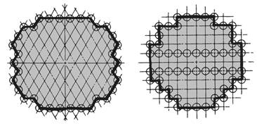
Perimeter of the tube layout measured stepwise in increments of one tube pitch from center-to-center of the outermost tubes. The figure shows the application to typical triangular and square tube patterns.
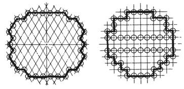
This value is required for the mechanical calculation of tubesheets according to ASME BPVC Section VIII Div. 1 chapter UHX.