Operation
Start Coil by ‘Programs’ / ‘COIL’ / ‘Coil type heat exchanger’
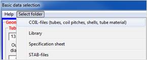
In this menu, you can determine the network paths for a network installation of COIL. COIL basic data (tubes, pitches, and shells), the tube sheet library and the properties module ‘S-TAB’.
After starting the program the "Basic data selection" dialog box appears.
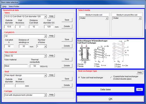
In this dialog box you can specify the type of heat exchanger, the geometrical data and media and select company standards.
The conception of the COIL program is that only few mouse clicks are needed to select type and basic design of the heat exchanger as well as tube-side and shell-side medium.
The following basic data can be selected:
|
Description |
Contents |
Entry (example) |
Meaning |
|
|
Tube dimensions |
List of tubes used by the manufacturer |
25 x 2 coil-shell 12 |
Outside diameter of tube Wall thickness Distance Coil-Shell Coil Diameter |
25 mm 2 mm 12 mm 250 mm |
|
Coil pitch DH |
Coil pitch Distance of windings W Number of tubes |
32 32 1 |
Coil pitch Distance of windings Number of tubes in the coil |
32 mm 32 mm 1 |
|
Shell dimensions |
List of shells used by the manufacturer |
114.3 X 3.6 |
Outside diameter of shell Wall thickness |
114.3 mm 3.6 mm |
|
Type of coil |
Type of displacement body |
Coil with cylinder Coil without cylinder |
||
|
Tube side medium |
property modules |
water |
||
|
Shell side medium |
property modules |
water |
||
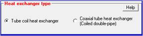
Select the type of heat exchanger you want to design
· Coil Heat Exchanger
· Coaxial Heat Exchanger
See also: Program features
Several standard tubes according to DIN standards are given.
The phrase 25 x 2 coil-shell 12 coil diameter 250 means:
·
Outside diameter of tube 25 mm
·
Wall thickness 2 mm
·
Minimum distance coil-shell and coil-cylinder 12
mm (This distance is not underrun while the calculation is running. This value
can be modified in the input mask afterwards.)
· Coil diameter 250 mm (This value is required to determine the standard shell, which is saved in the program. The coil diameter is recalculated
Several standard tubes according to DIN standards are given.
The phrase 20 X .75 / 12 X 1 / DW 220 means:
External tube:
· Outside diameter 20 mm
· Wall thickness 0,75 mm
Internal tube:
· Outside diameter 12 mm
· Wall thickness 1 mm
Coil diameter DW 220 mm
The coil pitch DH may be entered freely. It must not underrun the value of the outside diameter of the external tube.
COIL can calculate coil type heat exchangers consisting of a maximum of 5 parallel flown through tubes.
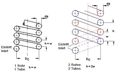
Coil pitch is always related to one tube. The distance of windings is the distance of the center of two adjacent windings of the coil. If the coil consists of only one tube, the distance is equal to the coil pitch. If the coil consists of nR tubes (nR £ 5), the following relation of coil pitch hand distance of windings w is valid:
h = nR · w
The coil length ls is calculated from the number of windings, N, number of tubes nR , coil pitch h and the distance of windings w:
lc = N · h + (nR-1) · w
You can change the number of tubes subsequently in the input mask.
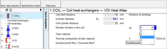
Here you may select the tube material and the according thermal conductivity. The unit of the thermal conductivity is [W/(m·K)].
To save a new material and its thermal conductivity, simply enter the data in the fields 'Tube material' and 'Thermal conductivity' and then press the 'Save' button.
Under shell diameter a lot of shells are predefined in accordance to DIN standards 2448 and 2458 for seamless and welded tubes.
The phrase 114.3 x 3.6 means
· Outside diameter of shell: 114.3 mm
· Wall thickness: 3.6 mm
If you have chosen "Free input / Design" for the shell the program automatically selects a shell from the list of shells during calculation of the heat exchanger.
By selecting the coil type, you select the design type of your coil heat exchanger, i.e. how the flow is guided around the coil. The following types can be designed:
· Coil with displacement cylinder
· Coil without displacement cylinder
Select the tube side and shell side media from the pull-down menu. The state of the media (liquid or gas), relevant for the calculation of the heat transfer, is set automatically. If you select 'Free input", "PROPER " or "STAB" (user-defined properties), you have to enter the state manually.
If "Free input“ has been selected for one of the media in the “Basic data selection “ mask, the properties of this medium have to be entered manually (see Manual input of properties "Free input").
The COIL standard package comprises several properties modules. See: The modules of COIL
You can enhance this list by adding further properties modules, which are not included in the standard package. The properties determination program PROPER (not included in the standard package) allows you to specify any mixtures of the data base and their components.
Furthermore, you can also enter properties manually by using the S-DAT module (see Manual input of properties "Free input").
Fouling resistances for water in shell and tube heat exchangers (m²K/W)
|
Temperature of heating medium |
Up to 120°C |
120–200°C |
||
|
Temperature of water |
50°C |
Over 50°C |
||
|
|
Flow velocity |
Flow velocity |
||
|
Cooling water |
≤ 1 m/s |
> 1 m/s |
≤ 1 m/s |
> 1 m/s |
|
Seawater |
0.00009 |
0.00009 |
0.00018 |
0.00018 |
|
Brackish water |
0.00035 |
0.00018 |
0.00053 |
0.00035 |
|
Cooling tower and artificial spray pond: |
|
|
|
|
|
Treated make up |
0.00018 |
0.00018 |
0.00035 |
0.00035 |
|
Untreated |
0.00053 |
0.00053 |
0.00090 |
0.00075 |
|
City or well water |
0.00018 |
0.00018 |
0.00035 |
0.00035 |
|
River water: |
|
|
|
|
|
Clean |
0.00035 |
0.00018 |
0.00053 |
0.00035 |
|
Normal |
0.00053 |
0.00035 |
0.00070 |
0.00053 |
|
Sewer |
0.00141 |
0.00090 |
0.00175 |
0.00141 |
|
Muddy or silty water |
0.00053 |
0.00035 |
0.00075 |
0.00053 |
|
Hard (over 250 ppm) |
0.00053 |
0.00053 |
0.00090 |
0.00090 |
|
Engine jacket |
0.00018 |
0.00018 |
0.00018 |
0.00018 |
|
Distilled or closed circle |
0.00009 |
0.00009 |
0.00009 |
0.00009 |
|
Treated boiler feedwater |
0.00018 |
0.00009 |
0.00018 |
0.00018 |
|
Boiler blowdown |
0.00035 |
0.00035 |
0.00035 |
0.00035 |
|
Cooling water |
Fouling resistance |
|||
|
Quench water |
0.00045 |
|||
|
Polyphosphate treatment |
0.00015 |
|||
|
Acid treatment |
0.00008 |
|||
|
Cold brine |
0.0002–0.00033 |
|||
|
Aqueous salt solutions |
0.0002–0.00033 |
|||
© Springer Verlag Berlin Heidelberg 2013
|
TEMA fouling resistances for oil refinery streams in shell-and-tube exchangers (m²K/W) |
|
|
Crude oil and vacuum unit |
|
|
a) gaseous |
|
|
Vacuum overhead vapors Atmospheric tower overhead vapors Light Naphtha |
0.00035 0.00018 0.00018 |
|
b) liquid Crude oil (desalted at 120°C. tube side velocity > 1.3 m/s) |
|
|
T < 120°C |
0.00035 – 0.0007 |
|
120°C <T < 175°C |
0.00053 – 0.0007 |
|
175°C < T < 230°C |
0.00070 – 0.00088 |
|
230°C < T |
0.00088 – 0.0011 |
|
Light gasoline |
0.00018 |
|
Kerosene |
0.00035 |
|
Heavy gas oil |
0.00035 – 0.00053 |
|
Gasoline |
0.00035 – 0.00053 |
|
Light gas oil |
0.00053 – 0.00088 |
|
Heavy fuel oils |
0.00088 – 0.0012 |
|
Vacuum tower bottoms |
0.0018 |
|
Atmosphere tower bottoms |
0.0012 |
|
Cracking and Coking |
|
|
Bottoms Slurry Oil (u>1.5 m/s) |
0.00053 |
|
Light Cycle Oil |
0.00035–0.00053 |
|
Light Coker Gas Oil |
0.00053–0.0007 |
|
Low-boiling liquid products |
0.00053 |
|
Overhead vapors |
0.00035 |
|
Heavy cycle oil |
0.00053–0.0007 |
|
Heavy Coker Gas Oil |
0.0007–0.00088 |
|
Catalytic Reforming, Hydrocracking and Hydrodesulfurization |
|
|
Reformer Charge |
0.00027 |
|
Reformer Effluent |
0.00027 |
|
Hydrocracker Charge and Effluent |
≥ 0.00035 |
|
Hydrodesulfurization Charge and Effluent |
≥ 0.00035 |
|
Recycle Gas |
0.00018 |
|
Overhead vapors |
0.00018 |
|
Liquid product spec. weight > 50°API |
0.00018 |
|
Liquid product 30°API-50°API |
0.00035 |
|
TEMA fouling resistances for oil refinery streams in shell-and-tube exchangers (m²K/W) |
|
|
Light Ends Processing Streams |
|
|
Overhead vapors and gases |
0.00018 |
|
Liquid products |
0.00018 |
|
Alkylation Trace Acid Systems |
0.00035 |
|
Absorption Oils |
0.00035–0.00053 |
|
Reboiler Streams |
0.00035–0.00053 |
|
Visbreaker |
|
|
Overhead vapor |
0.00053 |
|
Visbreaker bottoms |
0.00176 |
|
Catalytic Hydro Desulfurizer |
|
|
Charge |
0.0007–0.00088 |
|
Effluent |
0.00035 |
|
H.T. Sep. Overhead |
0.00035 |
|
Liquid products |
0.00035 |
|
Stripper Charge |
0.00053 |
|
Naphta Hydro Desulfurizer |
|
|
Charge |
0.00053 |
|
Effluent |
0.00035 |
|
Naphtas |
0.00035 |
|
Overhead |
0.00025 |
|
HF alkylation |
|
|
Charge |
0.00018 |
|
Head condenser |
0.00018 |
|
Product cooler |
0.00018 |
|
Product reboiler |
0.00035 |
|
Reactor charge |
0.00035 |
|
Lube Oil Processing |
|
|
Solvent Feed Mix |
0.00035 |
|
Feed stock |
0.00018 |
|
Raffinate |
0.00018 |
|
Tar |
0.00053–0.00088 |
|
Solvent |
0.00018 |
|
Desulfurization |
|
|
Overhead |
0.00018 |
|
Cooler |
0.00028 |
|
Return evaporator |
0.00028 |
© Springer Verlag Berlin Heidelberg 2013
|
Fouling resistances for various fluids (m²K/W) |
||
|
Oils: |
Fuel Oil No.2 |
0.00035 |
|
Fuel Oil No.6 |
0.00088 |
|
|
Transformer oil |
0.00018 |
|
|
Engine Lube oil |
0.00018 |
|
|
Hydraulic Oil |
0.00018 |
|
|
Quench Oil |
0.0007 |
|
|
Pitch |
0.0008 |
|
|
Tar |
0.0009 |
|
|
Vegetable Oil |
0.00053 |
|
|
Gases and Vapors: |
Steam (non-oil bearing) |
0.0000 |
|
Steam (oil bearing) |
0.00018 |
|
|
Refrigerant vapors (oil bearing) |
0.00035 |
|
|
Alcohol vapor |
0.0000 |
|
|
Organic vapor |
0.00009 |
|
|
Ammonia |
0.00018 |
|
|
Carbon dioxide |
0.00035 |
|
|
Combustion gas (coal) |
0.00018 |
|
|
Combustion gas (natural gas) |
0.00018–0.00035 |
|
|
Diesel exhaust gas |
0.0018 |
|
|
Synthesis Gas |
0.0018 |
|
|
Compressed air |
0.00018–0.00035 |
|
|
Natural gas |
0.00018 |
|
|
Nitrogen |
0.00018–0.00035 |
|
|
Stable column overhead product |
0.00018–0.00035 |
|
|
Fouling resistances for various fluids (m²K/W) |
||
|
Liquids: |
Refrigerant |
0.00010–0.00018 |
|
Organic heat transfer liquid |
0.00018–0.00035 |
|
|
Ammonia (non-oil bearing) |
0.00018 |
|
|
Ammonia (oil bearing) |
0.00053 |
|
|
Methanol solution |
0.00035 |
|
|
Ethanol solution |
0.00035 |
|
|
Glycol solution |
0.00035 |
|
|
LPG. LNG |
0.00018–0.00035 |
|
|
MEA- and DEA solution |
0.00035 |
|
|
DEG- and TEG solution |
0.00035 |
|
|
Stable column side stream |
0.00018–0.00035 |
|
|
Stable column bottom stream |
0.00018–0.00035 |
|
|
Caustic solutions |
0.00035 |
|
|
Black liquor |
0.0007–0.0014 |
|
© Springer Verlag Berlin Heidelberg 2013
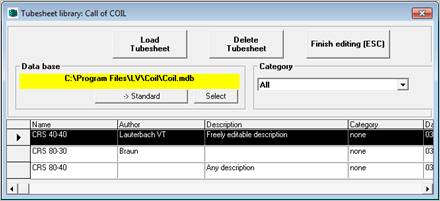
The "Data base" button allows you to transfer the geometrical data of an exchanger you have already designed from the data base to the program. A table is shown, where you can select the desired exchanger by clicking it.
By clicking the "Load Tubesheet" button, the geometrical data are transferred to the COIL program. The "Finish editing" button closes the table and you switch back to the "selection of basic data ". Geometrical data you have already entered in this mask are overwritten and the geometrical data cannot be changed manually.
>> Please note that creating,
editing and saving of a record is only possible in the COIL module
(see Using the data base).
After having finished the basic data selection, please confirm with OK. Another selection mask is displayed
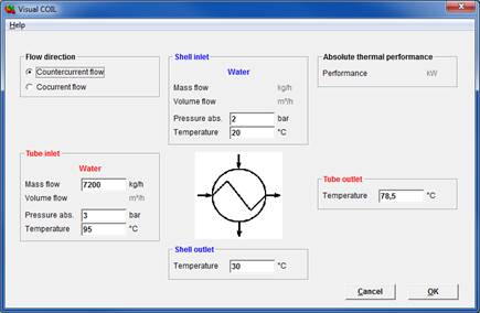
You can enter your system data (temperatures, pressures, mass flow or performance). These values can also be entered in the COIL input mask.
Confirm your selection with "OK" and the COIL input mask is displayed.
TIP: Conversion of units
A click on the unit or a double click on the input field the conversion of units is activated.
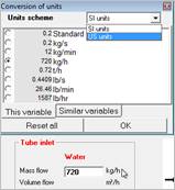
Enter the values in the unit you have at hand; e.g., mass flow in kg/h. The value is immediately converted in all other displayed units. The unit with the activated checkbox is displayed on the mask and will be used for the documentation.
Please confirm your input with 'ENTER'.
|
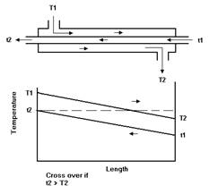
Countercurrent flow Heat exchangers with counter current flow have a higher thermal efficiency than cocurrent flow heat exchangers. In countercurrent flow heat exchangers it is possible, that the outlet temperature of the cold medium exceeds the outlet temperature of the hot medium. This is called 'Temperature Cross Over'
|
|
|
Cocurrent flow In cocurrent flow heat exchangers the outlet temperatures of the cold and the hot medium approach asymptotically.
|
|
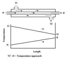
The cocurrent flow does not allow a switching of temperatures and the thermal efficiency is lower than in countercurrent flow. However there are some characteristics of cocurrent flow heat exchangers that are significant:
1. Cocurrent flow creates a more constant wall temperature than the countercurrent flow.
2. The maximum wall temperature is lower than in countercurrent flow.
3. This avoids unintended over or under temperatures. This is most important for food processing where the temperature of the medium has to stay within a certain range to avoid protein coagulation.
With the COIL input mask, you control the calculation run. From this mask you can switch to all other modules of the software package.
The mask comprises all required input possibilities for the calculation of a heat exchanger. The input values are also displayed on the masks of the according calculation module. They might be changed or entered in the modules as well. Switch to the module as described in the "ATLAS" manual ("ATLAS" menu - "chapter" or simply click the tab).
The COIL module has a special menu called "Basic input".
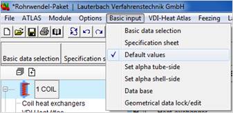
This menu item brings you back to the "Selection of basic data".
With this menu item all data are transferred to MS EXCEL and displayed as specification sheet.
You can rename all cells as you desire and save the sheet as template. Do not change the order of the cells, as the program otherwise does not write the data to the correct cell.
The ‘Default values’ option is activated by ticking the menu item.
If the option is activated COIL uses standardized dimensions and default values for the design of a heat exchanger. For example, if the user enters a new coil diameter during the optimization, COIL selects the shell, which just has enough space for this coil.
If the option is activated again, the heat exchanger is automatically recalculated. COIL uses again a standardized shell.
If the heat transfer coefficient in the tubes (alpha i) is known from other sources (such as measurements) and therefore doesn't need to be calculated by COIL, this value can be entered into the field "Heat transfer coefficient (inside)“ in the COIL input mask after clicking the option "Set alpha tube-side“.
In this case the user interface "Clear value of variable" is not displayed, i.e. no recalculation to a dependent variable like e.g. the tube diameter is done. If you click again the option "Set alpha tube-side" the heat transfer coefficient in the tubes is calculated by COIL.
If the heat transfer coefficient around the tubes (alpha a) is known from other sources (such as measurements) and therefore doesn't need to be calculated by COIL, this value can be entered into the field "Heat transfer coefficient (outside)" in the COIL input mask after clicking the option "Set alpha shell-side".
In this case the user interface "Clear value of variable" is not displayed, i.e. no recalculation to a dependent variable like e.g. the tube outside diameter, coil diameter, coil pitch, etc. is done. If you click again the option “Set alpha shell-side“ the heat transfer coefficient around the tubes is calculated by COIL.
You can save the geometrical data entered in the COIL input mask in a data base and load it for another calculation.
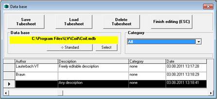
By clicking the button 'Save Tubesheet' the geometrical data (outside diameter of shell, wall thickness of shell, outside and inside diameter of tube, coil diameter, coil pitch, number of turns etc.) entered in COIL are saved to the data base.
By clicking the button 'Load Tubesheet' the geometrical data highlighted in the table are transferred to the COIL input mask. With the button 'Finish editing' or by pressing the ESC key you switch back to COIL.
If a tubesheet is loaded from the data base, it is always locked. This means the geometrical variables of the heat exchanger are fixed and can neither be overwritten in the input mask nor recalculated by the program. The fields concerned are highlighted in grey on the input mask.
If modification of such variables is desired click the menu item ‘Geometrical data lock/edit’ to unlock the tubesheet for editing.
If "Free input“ has been selected for one of the media in the “Selection of basic data“ mask, the properties of this medium have to be defined. After entering the inlet and outlet temperature and the pressure on the COIL mask the S-DAT module is activated automatically. Pressure and mean temperature are transferred already.
Required data
· Liquids and gases (single phase media):
For calculating the heat transfer and the pressure drop, properties at mean temperature and at wall temperature are required. At first start of S-DAT the wall temperature is unknown.
Please enter only the properties at mean temperature at first. As soon as the data input is complete, the program switches automatically back to the COIL mask. After the wall temperature has been calculated please switch to the S-DAT module by clicking on the according tab strip and complete the properties at wall temperature. If you do not enter the properties at wall temperature, the values are replaced by the values at mean temperature for calculating the pressure drop and the heat transfer.
In this case the accuracy of the calculation decreases. Especially with viscous media like oils greater errors might occur.
· Condensation of pure substances
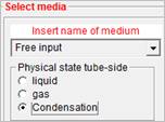
When condensing pure substances, the properties of the vapour and the properties of the condensate at condensation temperature are required.
As soon as the data input is complete, the program switches automatically back to the COIL mask.
If you have selected “Free input“ for both exchanger sides two S-DAT modules are created.
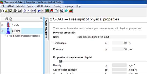
The first value block contains the information about the quantities, pressures and temperatures of both media. The values can be entered in any order.
In most cases the mass flows and temperatures are already known, which means that the heat balance is fixed. However, the exact temperatures or quantities are specified only by the properties used in the program, i.e. the last temperature or quantity which remains to be entered is calculated by the program to complete the heat balance.
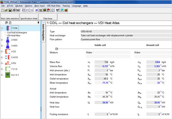
COIL input mask (heat balance)
The second value block contains the geometrical data of the coil type heat exchanger.
If you have already selected the tube and shell dimensions in the 'Selection of basic data' mask or if you have selected an exchanger from the data base, the geometrical data are already entered.
If not, you have to enter the data manually.
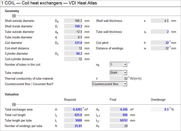
COIL input mask (geometrical data)
See also:
Coil pitch, distance of windings and coil length
The calculation ends as soon as the length of the exchanger is determined. This is the required length. The required length is the theoretical length, which is necessary to transfer the required performance. Now you have to enter the standard length (final length). With this length, the exchanger is calculated again and a new required length is determined. The difference between the two lengths shows the ‘reserve’ of the design.
Usually, the difference between final size and required size is expressed by a "substitute fouling rate", but this is not very specific. The "length reserve" is directly proportional to the area and represents a tangible measure of the reserve.
After you have entered the diameter of the inlet and the outlet nozzle, the tube-side and shell-side pressure drop is being calculated.
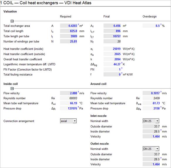
COIL mask (results)
The calculation can be directed by modification of the corresponding variables. The quality of the calculation can be enhanced e.g. by a "parameter study" informing how the exchanger responds when the process parameters are modified.
The COIL program can calculate a condenser with condensation of any pure substance.
For the calculation of the condensation process, it is important that the vapour enters the condenser with saturated steam temperature, which means not superheated, and that the condensate leaves the condenser with the same temperature, which means not subcooled.
If the vapour enters the condenser superheated and the condensate leaves the condenser subcooled, the condenser has to be divided into three zones. The desuperheating zone, the condensing zone and the subcooling zone. These zones have to be calculated separately with the COIL program. The complete transfer area is the result of the areas of the single zones.
If ‘Saturated steam’ or ‘NH3 condensation’ or ‘CO2 condensation’ have been selected in the ‘Basic data selection’ dialog box as condensing medium, a condensation of saturated steam (water steam) resp. ammonia or Co2 is presumed and COIL selects the condensation set-up to calculate the heat transfer. The condensation pressure Psat or the condensation temperature Tsat is required as input value. The properties of the steam and the condensate are calculated automatically.
For any pure substance to be condensed, select "Free input" for the condensing medium and ‘Condensation’ for the physical state in the "Basic data selection".
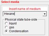
In the COIL input mask or in the ‘Visual COIL’ form, you have to enter the condensation pressure as well as the condensation temperature. Then the program switches to the S-DAT module automatically. Enter the properties of the condensate (boiling liquid) into the upper part and the properties of the vapour and the enthalpy of evaporation at the lower part.
As soon as you have entered all required data, the program switches back to the COIL mask.
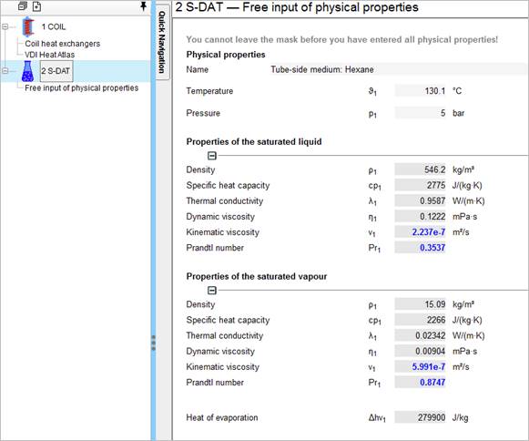 >> The pressure drop on the condensing side
is not calculated.
>> The pressure drop on the condensing side
is not calculated.