FEM program
Some problems in pressure vessel design cannot or only insufficiently be solved by using the standard equations of the according code. With these problematic cases, often an FE calculation is the only way to come to a solution. This calculation is usually quite complex and requires a certain amount of experience with the interpretation of the results.
We offer an integrated FE calculation for several standard problems like nozzles with external loads on cylindrical shells or domed heads. This FE calculation has improved net and graphics options and provides the following calculation options:
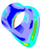
Reinforcing pads, oblique nozzles and oblique and tangential nozzles with / without reinforcing pads on cylindrical and spherical shells and Kloepperboden type and Korbbogenboden type (tori-spherical) heads
The approaches of the WRC bulletin 107 base on measurements of several geometrical data of shells and nozzles. It is obvious that you cannot measure all possible configurations. Therefore, you can use these approaches to a limited extent only.
This is the reason why LV has integrated a data interface to the FEM module into the WRC / WRCK module, which is also running as a standalone module.
|
Geometrical options |
· Vertical and oblique nozzles on cylindrical shells · Vertical and oblique nozzles on spherical shells · Vertical nozzles on tori spherical and semi-ellipsoidal heads · Oblique nozzles on tori spherical and semi-ellipsoidal heads · Offset / tangential nozzles on cylinders, spheres and domed heads · Considering reinforcing pads
|
|
Possible loads |
· Forces and moments at nozzle · Internal pressure · Thermal load · Fatigue stress
|
|
Calculation and detailed documentation |
· Calculation with FEM (Sparse Solver) with more than 120000 degrees of freedom · Calculation with shell elements of finite thickness · Free selection of nods and number of elements · Stress analysis per AD S4 / ASME VIII-2 · Fatigue analysis per AD S2 / ASME VIII-2 · Documentation per AD S4 /ASME VIII-2
|
· Output of geometrical data as DXF file
· Interfaces to other FEM software (Cosmos, Ansys)
· 3D visualization of the results and geometry as DirectX, GDI or HPGL
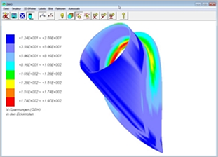
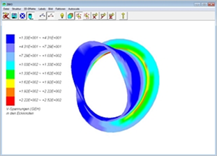
· Visualization of the stresses / movements in deformed and normal system
· New: External calculation with ANSYS
|
|
|
|
Fig. 1 Offset nozzle on cylinder |
Fig. 2. Vertical nozzle with
reinforcing pad |
|
|
|
|
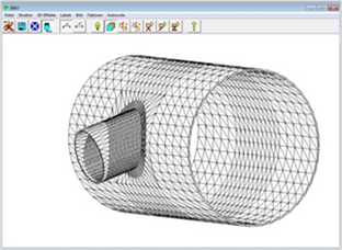
Fig. 3 Oblique nozzle on cylinder
|
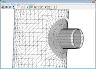
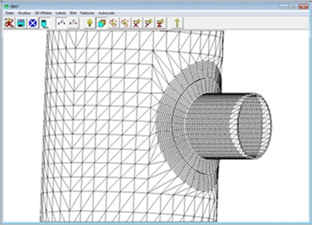
Fig. 4 Vertical nozzle on cylindrical shell, displaced. |
|
|
|
|
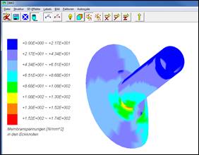
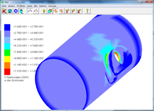
Fig. 5 'Von Mises' stress at nozzle area |
Fig. 6 Movement in Y direction |
|
|
|
|
Fig. 7 Tangential nozzle |
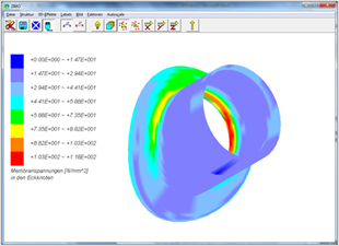
Fig. 8 Stresses in tangential nozzle |
|
|
|
|
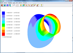
Fig. 9 Visualization of deformed system „tangential nozzle" |
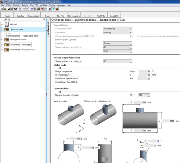
Creating FE model:
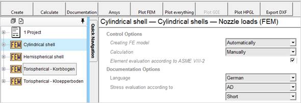
· Automatically: As soon as there are enough user inputs to create the FE model, the program creates the model automatically. The program will display a message, which the user has to confirm.
· Manually: The user must start the model creation manually by pressing the “Create” button.
Calculation:
· Automatically: As soon as there are enough user inputs to start the calculation, the program starts the calculation automatically. The program will display a message, which the user has to confirm.
· Manually: The user must start the calculation manually by pressing the “Calculate” button.
Element evaluation according to ASME VIII-2
Activate this option even with an AD calculation to receive results, which are comparable to other commercial FE programs, as these other programs calculate based on ASME.
Language
· German: FE Documentation in German
· English: FE Documentation in English.
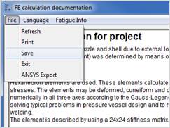
You can save the FE documentation as RTF file by selecting ‘File – Save”. This RTF file is integrated into the FEM documentation and can be printed as one whole file.

Stress evaluation acc. to
· AD: Stress evaluation acc. to Merkblatt S4
· ASME: Stress evaluation acc. to ASME VIII-2
· Short: Overview of stresses and their evaluation
· Detailed: Includes additionally the documentation of the decomposition of stresses in their components and hints concerning the stress categories.
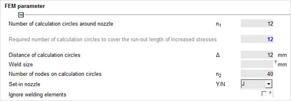
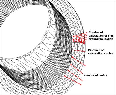
Control the density of the mesh by adjusting the FEM Parameters.
Distance of calculation circles is the width of elements. The width may be max. 2* wall thickness and min. 0.7 * wall thickness.
The number of support points (elements) around the nozzle must be divisible by 40.
The number of nodes must be divisible by 8 with a minimum of 36 and a maximum of 96.
Weld size: The variable weld size defines the discontinuity between nozzle and shell. Usually this is the size of the weld in shell direction. You can exclude this area from the stress evaluation by using the tick box ‚Ignore welding elements‘.
The user might decide for himself whether he wants to consider these stresses or not.
Loads apply at:
|
S – End of nozzle:
|
All forces and moments apply at end of nozzle. |
|
E – Sectional plane: |
Forces and moments apply at the sectional plane between nozzle and shell. In most cases, it is not possible to define this plane unmistakably. In such a case, please use a nozzle of a length of 100mm and apply the loads at the end of the nozzle (procedure according to NozzleSpecApp).
|
|
A – Intersection with axis: |
Loads apply at the intersection of the shell axis and the nozzle axis. Only valid for piping systems. |
|
R – Sectional plane with rigid elements: |
The sectional plane is formed by rigid elements. This enables you to describe integral attachments such as cams or trunnions. |

For performing an FE calculation, please use the first three buttons from left to right.
1. Create (the FE model)
2. Calculate the created FE model
3. Documentation of the model (stress evaluation and graphics)
|
|
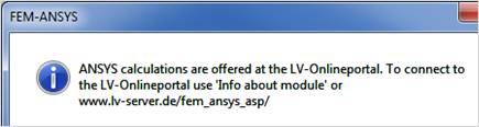
Input into an EXCEL file with an external ANSYS calculation using the LV online portal.
|
|
|
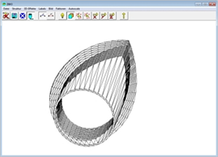
Only the nozzle is shown in the FEM graphics.
|
|
|
Nozzle is shown with shell in the FEM graphics. |

|
|
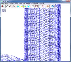
GDI graphics with node number is shown.
|
|
|
FEM graphics is shown (Hewlett Packard Graphics Language)
|