Quickstart
|
Action |
What you see |
Explanation |
|
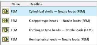
Select the type of your basic body. |
|
Parametric models are stored for these types of basic bodies. |
|
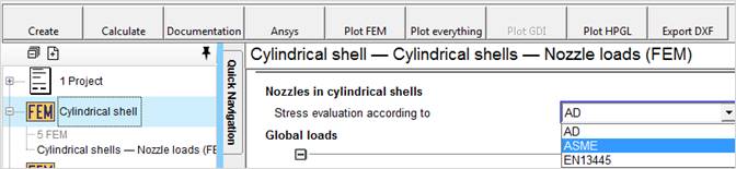
Enter all relevant data in the module mask. Model (mesh) Create, Calculate and Documentation is controlled by the buttons. |
|
According to the state of your input the according buttons are activated. |
|
Action |
What you see |
Explanation |
|
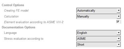
Setting of calculation options and documentation options |
|
Set here if you want to calculate acc.to AD 2000, ASME or EN 13445 and select the documentation language English or German. |
|
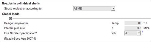
Input of boundary conditions |
|
|
|
Action |
What you see |
Explanation |
|
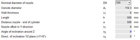
Input of geometrical data |
|
|
|
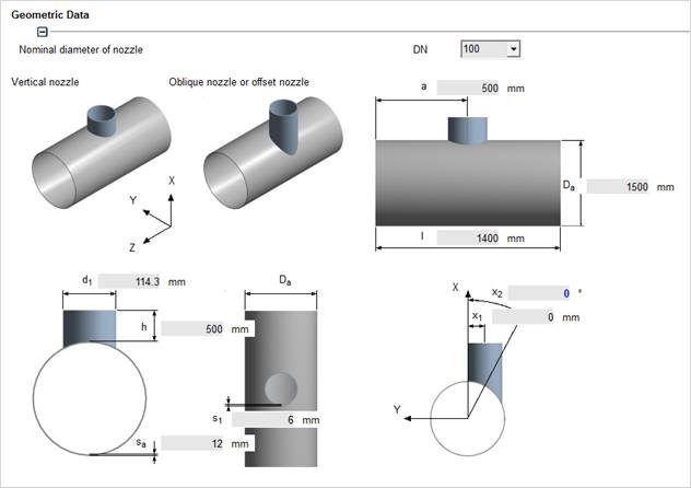
Enter shell data |
|
Especially with very long shells, the considered length can differ from the actual shell length. |

|
Action |
What you see |
Explanation |
|
Use nozzle specification |
|
If you use the nozzle specification from the NozzleSpecApp, the forces and moments are taken from this specification and entered automatically. |
|
Enter nozzle data |
|
Geometrical data and position of the nozzle. When you are using DIN nozzles, you can select the nominal diameter DN. |
|
Specify tangential nozzle |
|
|
|
Specify reinforcing plate |
|
If there is no reinforcing plate, just leave the fields empty |



|
Action |
What you see |
Explanation |
|
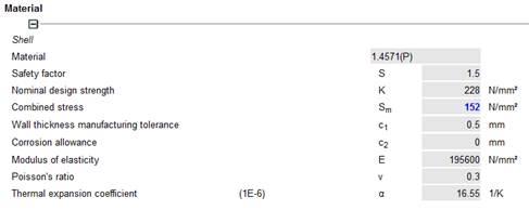
Input of materials of shell, nozzle and reinforcement |
|
Material data are called up from the material data base |
|
Action |
What you see |
Explanation |
|
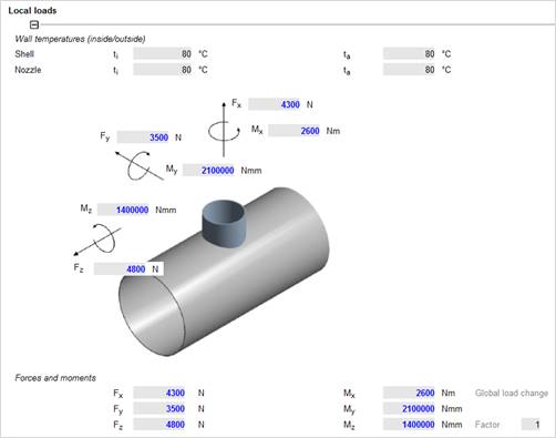
Entering the local loads |
|
In case you are using the nozzle specification, here the forces and moments have been already entered. |
|
Action |
What you see |
Explanation |
|
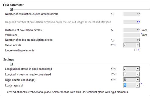
Enter mesh data
Consider longitudinal stress due to internal pressure.
Selection where loads apply
FEM Parameter |
|
FEM Parameter |
|
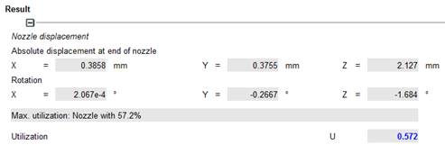
Result Displacement at nozzle end and the maximum utilization. |
|
|
|
Action |
What you see |
Explanation |
|
Detailed results |
|
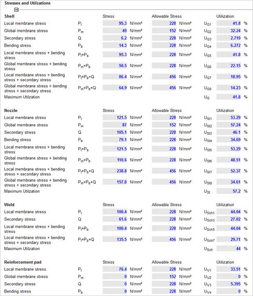
Stresses and utilization of shell, nozzle weld and reinforcement pad if applicable. |
|
Action |
What you see |
Explanation |
|
Documentation |
|
You can save the FE documentation as RTF file by selecting ‘File – Save”. This RTF file is integrated into the FEM documentation and can be printed as one whole file. |

|
Action |
What you see |
Explanation |
|
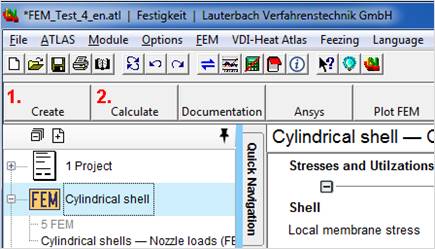
1. Create the FE model
2. Start the FEM calculation |
|
This is the central mask of the FE calculation.
All actions can be controlled here |
|
Action |
What you see |
Explanation |
|
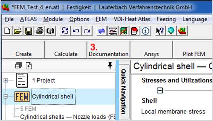
Select ‘Documentation’ |
|
When the FEM calculation is finished the documentation can be created. |
|
Action |
What you see |
Explanation |
|
Now select
„Membrane stress“ |
|
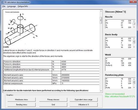
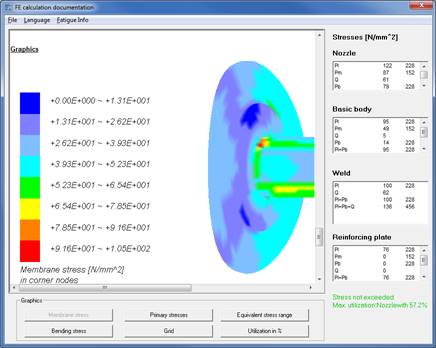
In this mask, the documentation is created automatically.
As soon as the mask is loaded you receive information about the utilization of your configuration. |
|
|
|
|
|
Action |
What you see |
Explanation |
|
Move the mouse with pressed left key to change the size.
Move the mouse with pressed right key to rotate the model.
|
|
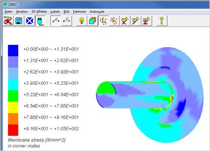
Mask for presentation of stresses and displacements.
|
|
Click on „Display node stress“ |
|
This button activates the presentation of stresses.
Further buttons: Element stresses and displacements |
|
Action |
What you see |
Explanation |
|
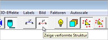
Press the button „deformed
|
|
You may freely resize and rotate the 3D stress model with the mouse. For rotation keep the right mouse button pressed, for sizing the left mouse button, and move the mouse over the model. |
|
Use the Copy button |
|
This button copies the current view. An automatic copying of the graphics is not possible. You may freely position the view of the nozzle at your desire. |
|
Action |
What you see |
Explanation |
|
Here you may also print or save the documentation or cancel the presentation. |
|
Stresses and views can be easily integrated into the documentation.
Additionally you may also enter your comments or own CAD graphics |
|
Action |
What you see |
Explanation |
|
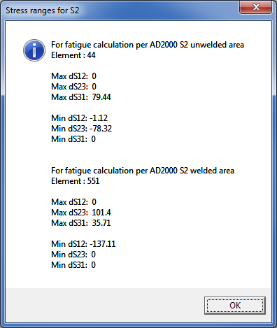
Press „Fatigue Info“ To show the S2 stress range |
|
|
|
Action |
What you see |
|
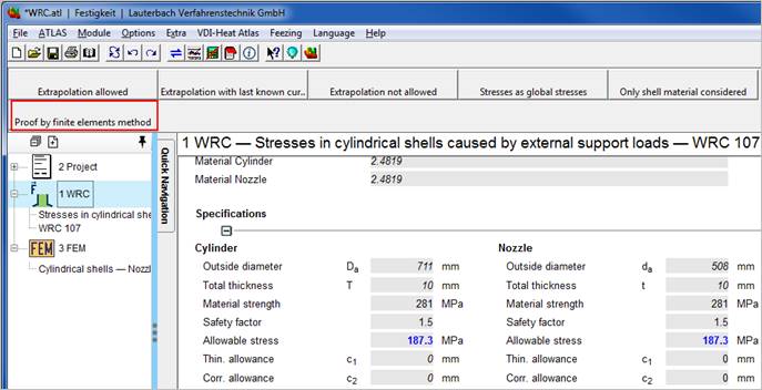
In the LV module WRC Press the button „Proof by finite elements method“ The calculation of stresses in cylindrical shells with nozzles under nozzle load is too inaccurate with WRC or even impossible.
|
|
|
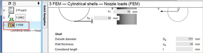
In this case you can easily start an FE calculation. Values already entered into the WRC module are automatically transferred to the FEM module.
|
|
|
Action |
What you see |
Explanation |
|
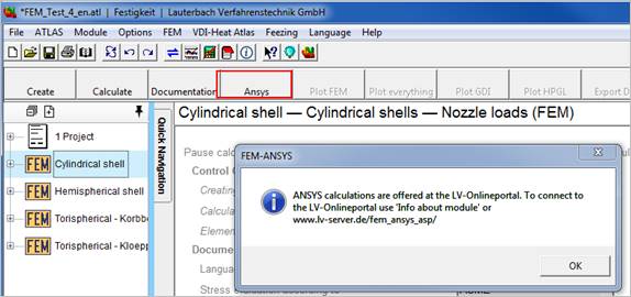
Press the ANSYS button in the FEM module. |
|
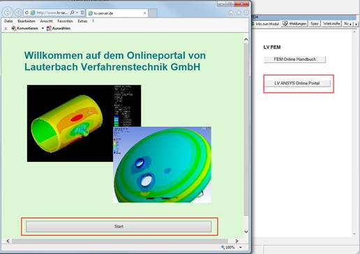
You will be connected to the LV ANSYS Online Portal.
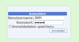
For performing an ANSYS calculation, a customer login is required. Give us a call or write an email.
In the customer area of the LV server you may start your ANSYS calculation subject to a certain fee and call up your documentation as PDF file |
|
Connect to the LV ANSYS Online PORTAL by clicking the link in the Help browser
You receive the customer login data from the LV team. |
|
|