Special problems
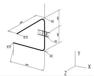
Given is a pipeline NW 100 (OD 114.3 mm) with 7.1 mm wall thickness. The pipeline is made of St35.8 throughout and conveys hot water of 200°C at 20 bar.
The pipe starts at a pump flange, runs 4000 mm in direction X , rises vertically 4000 mm, passing a ceiling lead-through after 2000 mm. After the riser, the course changes to direction Z, whereby after 4000 mm the line connects to a hot water tank.
The pump connection and the tank connection are considered rigid (fixed points).
The sheets are standard 3D sheets.
The fixed points, the deflections and the ceiling penetration were given node designations according to the above isometry.
1. Starting Excel with PIPE Add-in.
2. From "Pipe" menu "New input" submenu
3. Enter the first pipe route from node 10 to node 20:
|
From |
According to |
Dx [mm] |
Dy [mm] |
Dz [mm] |
Radius / T-piece |
|
10 |
20 |
4000 |
S |
The start and end nodes and the length of the line to the apex have been entered. Here sits an arc type "S" (Short Bend = 3D ).
The pipeline and the boundary conditions are specified in the "Special data" column. Double-clicking on this column activates the input help.
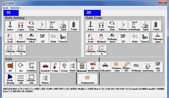
In this help about the corresponding switches
· Point 10 defined as anchor
· Outer diameter and wall thickness specified
· Calculates the weight
· Pressure and temperature entered
· the pipe material is specified via the database.
After completing the entries, you will receive the entry:

4. enter the riser to the ceiling passage, from node 20 to node 30 upwards direction Y 4000 mm. Node 30 is the ceiling passage. This is designed in such a way that the pipeline can move freely vertically, but is hindered in its movement horizontally by the bushing. This obstruction is defined with the input help and the "Bearing" button at node 30.
The entire input appears as follows:

Before the bushing, the pipeline now rises by a further 2000 mm and is then deflected, with a 3D bend.
Input:

Finally, the connection to the hot water tank follows, with a pipe section of 4000 mm in direction Z. Point 50 is again an anchor.

The file is saved under the name Test (Excel convention).
From the "Pipe" menu, the "Calculation" option starts the calculation of the pipeline.
After the end of the calculation the program creates the workbook
"TestErg.Xls".
This workbook contains the results of the calculation in the various tables,
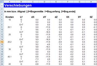
e.g. table "Displacements" the movement of the pipe during
installation and start-up, marked by the load cases G (weight) and T
(temperature).
|
|
The pipeline does not move at nodes 10 and 50. These are the fixed points. At node 30, the line moves only in direction Y as required, 12 mm downwards in the weight load case, and performs virtually no movement in the temperature load case.
|
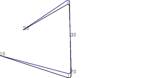
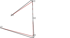
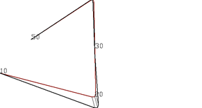
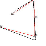
These movements can be displayed most effectively using the "Graphic" option from the "Pipe" menu:
|
Graphic for the weight load case, where Blue the unformed and Black represents the deformed line.
|
|
|
Graph for the thermal load case.
Red here is the undeformed line.
|
|
|
Graphic for the load case combination:
Red is again the undeformed line. |
|
The PIPE program is designed to require as little input as possible. This saves working time and reduces input errors.
To illustrate this, here is a case study:
The connection to the tank cannot be made in NW 100, but must be realized in NW 50. For this purpose, the pipe must be reduced accordingly shortly before the connection.
Procedure:
In Excel, a row is inserted between nodes 40 and 50 (Excel convention).
The line section from node 40 now no longer leads directly to node 50, but initially only to an intermediate node 45 with the length 3000.

The following line is corrected. It leads from the inserted node 45 to the fixed point 50, but now only has the length 1000 mm. In addition, the NW, the wall thickness and thus the weight have changed.

From node 45, the pipe geometry and weight are modified. This change is now valid for all possibly following pipes until it is modified again with new values.
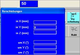
The connection on the hot water tank is not fixed, but the nozzle itself performs a movement during start-up due to the heating of the tank. The line must follow this nozzle movement. This is realized by the keyword DEL.
|
Input example
The line is forced at node 50 8 mm pressed upwards |
|
|
This results in the input table (excerpt)
|
|

After the calculation you will get the following results for the movements in the combination load case: (excerpt)
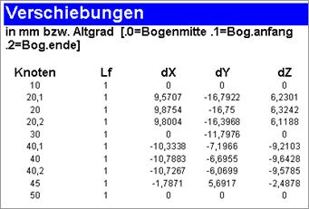
In the above example, it can be seen that the pipe undergoes strong movements at node 20, which must be carried by the pump flange at node 10. This would overload this flange or damage the pump shaft. A spring should therefore be installed at node 20 in such a way that node 10 does not have to bear any weight loads as far as possible. For this purpose, node 20 is modified in the 2nd input line. Double-click in special data. A spring is then selected for node 20.
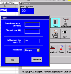
Since the spring characteristics are to be determined by the program, neither the spring constant nor the preload force (installation force) is specified. Only the bearing to be relieved is specified and Lisega is requested as the manufacturer of the spring. The last two entries are optional.
After the calculation, you will get the design data for the spring in the Hanger table:

The program suggests a spring with a spring constant of 266.6N/mm, which should be ordered with a preload of 2635N. The spring travel between installation and operation is 4.4 mm. This results in a load difference of 80%. This is generally not acceptable and must be checked.
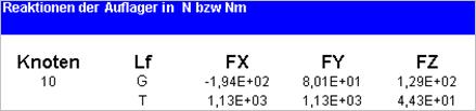
The pump nozzle load is now (excerpt)
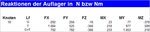
In the above example, although the pump flange has been almost relieved of load in the weight load case, the load on the flange in the thermal load case is still too great. This is due to the obstructed thermal expansion. Starting from the pump flange, the pipe would like to move in direction X, but this is prevented by the ceiling bushing. Only the pipe leg from node 20 to the bushing can absorb this expansion. In the real case, the bushing or the liner will of course not be designed in such a way that it sits over the pipeline like a fit, but there will be a clearance between the pipeline and the liner that can be used here.
|
The bearing 30 is provided with clearance The bearing 30 is allowed a clearance of 4 mm in each of the two directions of obstruction X and Z.
|
|
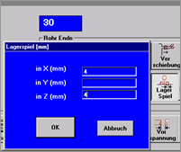
The input now has the form:

The keyword Gap always refers to the bearing in the same input cell, to bearing 30.
With this clearance, the bearing load is reduced again:
Stability calculation according to DIN 18800 part 4 for a pipeline section
Structure:
Stable #FromNode #AfterNode #Pressure #DistanceStiffenerRings#WidthStiffener #SurfaceStiffener
Example 1:
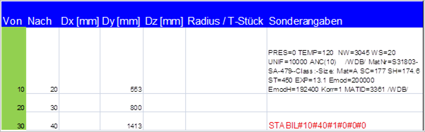
Above example stability calculation with
a cylinder from node 10 to node 40 ,
internal pressure 1 bar Ü , no stiffening rings.
Example 2
STABIL#10#40#1#2000#15#1500
Example stability calculation with a cylinder from node 10 to node 40, internal pressure 1 bar Ü, distance of stiffening rings 200 mm, thickness of rings = 15mm and the cross-sectional area of the ring is 1500 mm².
Procedure
Joint systems made of Angular expansion joints are best mapped with the Angular Knee expansion joints. Here, the rotation around the hinge pin is correctly mapped with the bellows as the torsion spring.
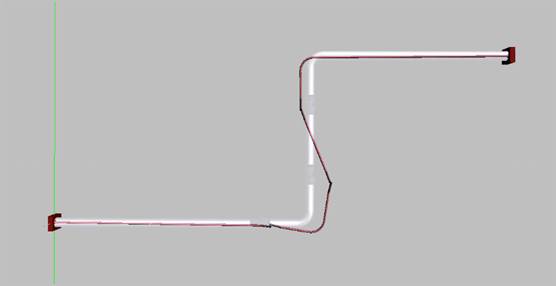
Here a joint system with 3 angular compensators.
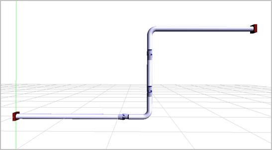
and the corresponding input:
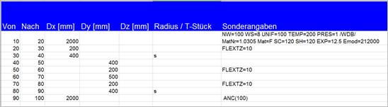
Use the freely selectable component (see description of any component) for expansion joints with multiple actions, such as angular and axial movements or inclined installation positions.