FAQ
|
Question |
Although the calculation was started after the input, only empty tables appear in the results folder. |
|
Reply |
The calculation could not be performed meaningfully because of an input error. |
Troubleshooting:
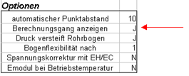
Switch on calculation tracking in the project sheet
After the calculation run, select from the PIPE menu the option Calculation run
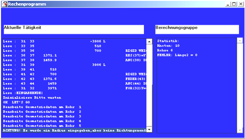
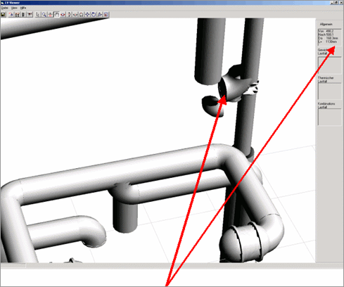
There seems to be a geometry error in the 450-500 node area
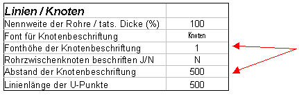
Node label
You get the better node labeling in DXF graphic mode.
|
Question |
How are the voltages represented graphically?
|
|
Reply |
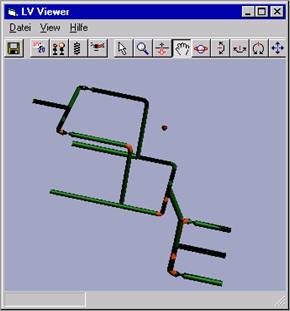
The color display can be controlled by the user when outputting AutoCad DXF graphics (project folder). The graphics card should be OpenGl capable. When outputting OpenGl graphics, only 3 color levels are displayed:
Surges: Red
|
|
|
|
|
Question |
How can axially displaceable joints be taken into account? |
|
Reply |
Sleeve connection: You take into account the additional axial forces with the keyword FOR. (Force button). In order to take into account the friction of the sleeve itself (friction spring), it makes most sense to consider this sleeve with the corresponding axial flexibility (friction spring) as a compensator incl. the axial additional forces. |
|
Question |
How can I change the coordinate system? |
|
Reply |
The settings can be made in the project folder or via the menu item "Coordinate system". In the Pipe program, the inputs are made in a Cartesian or cylindrical coordinate system. In the cylindrical coordinate system, only the pipe length in the plane and the direction angle (if necessary the height change) are required. You can rotate the coordinate direction by designating the displayed direction with e.g. -X. The headings of the columns are binding for the input. |
|
Question |
A flange verification according to DIN EN 1591 with the local moments and forces is to be performed. The keyword flange has been used for this purpose. However, there is no calculation. |
|
Reply |
The LV program package Firmness must be installed. Pipe calls module 1591 from this program and passes the corresponding values. Module 1591 must be enabled (purchased or FEEZING) |
|
Question |
Pipe creates a coordinate table for all pipes. The origin of the coordinate system (0,0,0) is always assumed for the first node. However, a pipe system (continuation of an existing system) is to be started at a defined point. |
|
Reply |
Use the keyword KO The keyword must be set in the second line if the main pipeline points are known. The corresponding node number is expected in the VON column. |
Example:
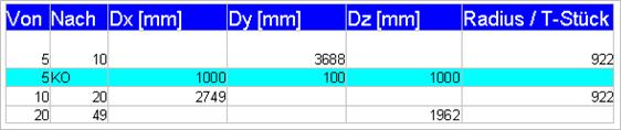
The start node 5 is assigned the spatial coordinates 1000,1000,1000 (X,Y,Z)
|
Question |
How do I proceed in case of bearing clearance with friction?
|
|
Reply |
A bearing clearance with friction is an undefined condition. The following happens in a bearing with clearance and friction: The temperature (general load) increases. The line moves in a frictionless state. In the case of friction, the movement is suppressed until the internal forces become greater than the static frictional force. In this case, the pipeline moves by the amount until the internal forces are again less than or equal to the dynamic frictional force. The internal forces and thus the bearing forces perform a sawtooth function. This sawtooth function has no defined intersection point with the movement - force line of the line in a bearing with clearance. Depending on the position of the curves, up to 2 intersection points = solutions can exist. Therefore, in the case of friction and bearing clearance, the user must decide whether to calculate with closed bearings or with open bearings. In any case, these are 2 load cases. |
|
Question |
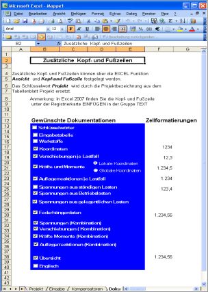
How can I customize the header and footer for my documentation? |
|
Reply |
Header and footer can be designed according to your own ideas. To do this, select the Docu table in the project folder. There you will also find further instructions. Caution: Excel cannot include graphics in the header and footer. The use of headers and footers can drastically slow down the processing speed of Excel. |
|
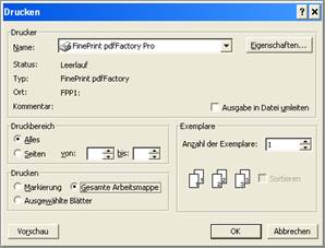
To print the entire folder, select the appropriate Excel option |
|
|
|
|
|
|
|
Question |
What is a fixed bearing? Why do I get different results when I enter a fixed bearing with the keyword RES (Restraint)?
|
|
Reply |
A fixed bearing is an anchor. All forces and moments are dissipated at an anchor. A rotation stop and a motion stop - with all 3 degrees of freedom blocked in each case - are equivalent to an anchor. |
Comparison runs
Input with anchor
|
RES(45)=X,-Y,Z GAPX=10 |
|
RES(50)=X,Z |
|
ANC(80) |
Result: Table support:
|
80 |
G |
914,7 |
-469,3 |
79,87 |
139,8 |
-103,6 |
6,811 |
|
T |
-1549 |
2638 |
-308,3 |
503,9 |
-966,4 |
-520,4 |
|
|
Wind |
3890 |
-3036 |
-995,1 |
-1530 |
1013 |
326,5 |
|
Input with stops |
|
RES(50)=X,Z |
|
RES(80)=X,Y,Z |
|
RED(80)=X,Y,Z |
Result: Table support:
|
80 |
G |
914,7 |
-469,3 |
79,87 |
139,8 |
-103,6 |
6,811 |
|
T |
-1549 |
2638 |
-308,3 |
503,9 |
-966,4 |
-520,4 |
|
|
Wind |
3890 |
-3036 |
-995,1 |
-1530 |
1013 |
326,5 |
Attention :
Keywords referring to stops are interpreted only once per bearing in a line. You can enter keywords in any line.
|
Question |
Why do I not get any stresses in the thermal load case for a pipeline clamped between two fixed points? |
|
Reply |
You cannot destroy a weightless and pressureless pipeline clamped between two fixed points by pure heating. It will eventually melt, but not be destroyed. These are the typical secondary stresses. Only the bending moments from the restrained strain are included in the thermal stresses. Note equation 13A in section 104.8.3 (B31).
|
|
Question |
How to model pressure-relieved axial expansion joints in PIPE? |
|
Reply |
For pressure-balanced expansion joints, the specification of the axial forces is omitted. The keyword FLFO can be omitted. The keyword can also be omitted if the compensator is secured against "flying apart" by tie rods. |
|
Question |
Why can't you use the keyword GAP and friction at the same time? |
|
Reply |
Simultaneous use of nonlinear bearings (GAP) and friction (nonlinear spring) is not possible. In a bearing clearance, the movement within the gap is again nonlinear due to friction. One could look for mathematical solutions here (conservatively), but the question would remain whether this still corresponds to reality. |
|
Question |
What must be entered to calculate arcs of type 2? |
|
Reply |
Shortened entries exist for type 3 and 5 bends. Type 3 = s, Type 5 = l For all other arcs, the radius must be entered in mm. |
|
Question |
When loading xls files from the PIPE I version I get an error message. |
|
Reply |
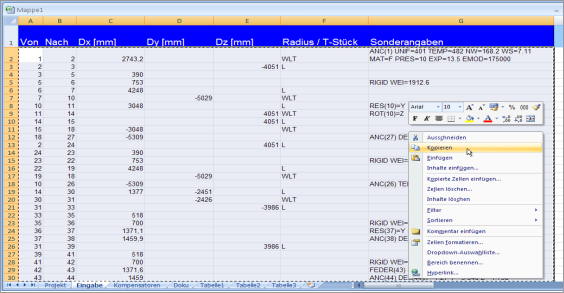
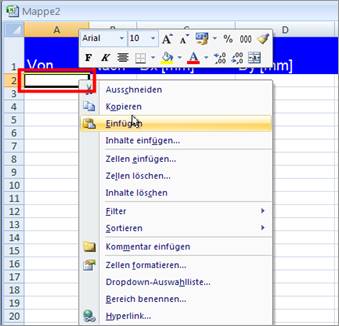
LV PIPE II is an Excel AddIn. Copy from the old EXCEL sheet the input rows (everything after the first row) and paste these cells into the new LV PIPE II input sheet after the first row. |
|
Question |
How do I form load combinations for non-linear bearings? |
|
Reply |
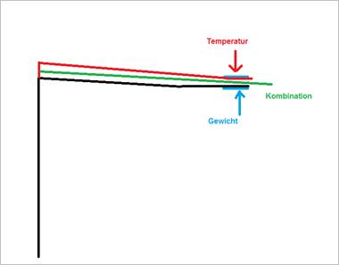
If a bearing clearance is used in a bearing, the combination load case of thermal load case and weight load case does not necessarily represent the sum of the individual loads.
Example: In the weight load case, a load is taken up in the bearing in the positive weight direction in the example. In the thermal load case, the bearing is loaded by a force in the negative weight direction. In the combination, the line lifts off but does not reach the stop of the bearing clearance limit. In this case, there is no bearing load in the weight direction. However, the sum of the bearing forces from weight and temperature load is different from zero. Intermediate solutions are also possible. |
|
Question |
Why are the load combinations I defined not calculated? |
|
Reply |
If a combination load case is not calculated, it is probably because the load cases involved are not enclosed in apostrophes (') in the calculation specification. See Load Cases/Load Case Combinations Excel 2007 and 2010 have a bug here by removing the first apostrophe after the input. |