Definitions
Describes a fictive point in the pipe run where a geometrical change (e.g. change of nominal width, T-piece) or a hydraulic change (e.g. supply or tapping point) occurs. All pipe gussets can be designated. If no name is entered the gussets are numbered consecutively. The automatic numbering starts with 1; zero cannot be used as a gusset number.
A gusset in the basic mask looks as follows:

A piece of pipe connecting two pipe gussets with each other.
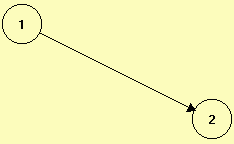
A pipe between two gussets is represented as follows:
Tee pieces as fittings (flow dividing or flow unification) can be simulated with the program.

defines a supply with constant pressure. The fluid quantity is adapted. This option simulates a high tank.
Symbol:

defines a tapping point. The quantity of extracted fluid is defined (l/s).
Symbol:

defines a point of supply (displacement-type pump).
The quantity of supplied fluid is defined (l/s).
Symbol:

simulates an open pipe end. Depending on the existing pressure a corresponding fluid quantity is let out.
Symbol:

defines a gusset with a circulating pump. A pump model controlled via a pump name has to be defined for each pump. For each pump gusset a pump model has to be specified.

Course of the Q - H curve for a pump model
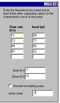
After leaving the mask for pump gussets, the mask for creating the pump model is displayed automatically. The pump name is entered automatically by the program.
For each pump model the appropriate operating ranges and the minimum and maximum delivery have to be entered. During the simulation this operating range of the pump is not left. If the pump is working outside the operating range the message “System does not converge” appears.
In this case another pump has to be selected for this application,
i.e. another pump model has to be created.
The pump sump describes the underwater level. Together with the geodesic height of the pump gusset it amounts to the inlet height.
The default value for the pump sump is “0”.
The Q-H curve of the pump is entered into a table. Please note that:
1. at least 3 points of the Q-H curve are entered.
the first point represents the zero head; this point is situated outside of the operating range of the pump and is needed for the iteration.
Enter the “Flow rates” (deliveries) increasingly and the “heads” decreasingly from the top downwards.
If a pump model has to be modified later, the pump mask and afterwards the mask for the pump model can be activated by double-click on the pump gusset.
In case of gas flow the input for the compressor is done with units modified correspondingly.
Name for a specified pump model
Minimum delivery possible, appropriate for the simulation of pumps.
This delivery has to be assumed to be > 0 and, consequently, it differs from the flow rate at the zero head.
Maximum delivery possible for the pump simulation.
If this value is exceeded an error message appears.
If the drawing mode is set, new pipe gussets and pipe runs can be drawn. A single gusset can be selected by mouse-click and moved.
The active mode can be selected in the "Edit" menu.
The active mode is displayed at the bottom of the basic mask:

In the selection mode parts or the whole pipe network can be moved.
The selected areas can also be deleted or copied to other programs
(e.g. WORD).
The active mode is selected in the "Edit" menu.
The active mode is displayed at the bottom of the basic mask: