Working in the basic mask
After starting the program the basic mask appears.
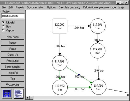
If a gas or vapour network has been selected some of the shown elements are not available.
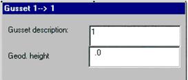
The gusset descriptions are numbered consecutively by the program. The geodesic height is copied from the gusset situated directly before and suggested as input value by the program. If you don’t wish to apply these suggestions you can overwrite them at any time. Any entry can be corrected after confirmation by activating the gusset mask with double-click on the relevant gusset and modifying the entry.
A pipe run is created by selecting the gusset centre with the left mouse key and dragging with pressed mouse key to the target gusset.
For the new pipe run the following input mask appears:
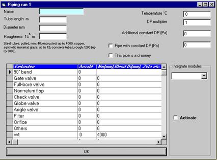
Tube length, diameter and roughness have to be entered first. When creating further pipes the same values are applied unless they are overwritten.
The number of existing internals has to be entered in the bottom part of the mask. For orifices the internal diameter has to be indicated, for other fittings a nominal diameter can be indicated if this value differs to the value of the pipe.
For other internals the zeta value is entered directly. Alternatively a fixed value for the pressure drop can be entered which is converted into a pressure drop factor considering the known flow velocity at the moment.
During iteration this value cannot be adapted to the respective flow velocity.
Additional internals can be entered in the pipe mask:
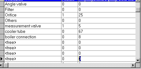
Below the line "Others" the default is set as "<free>". Further internals such as fittings can be entered here if required. In the right-hand column the zeta value has to be entered. When the pipe mask is called again these special internals are initialized with the number of pieces = 0. The special internals, as well as the standard internals in the first ten lines, are entered into the pipe list. They appear in the printout and when saving in a file (menu item "Documentation").
The input is restricted to approximately 50 additional internals.
The internals can also be entered directly into the file EINBAU.TAB with an editor.
BILD
On the right-hand side of the input mask for the pipe data additional modules, e.g. from the VDI heat atlas, can be selected to be integrated. It is possible to determine further data for the pipe run by using these modules.
This option cannot be used if the respective modules are not available!

The appearance of the link field may vary in the different versions of the program ROHRNETZ (PIPE NETWORK).
In addition to the usual information of normal gussets supply gussets provide the value for the supply pressure, in case of high tanks according to the geodesic height.
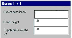
The supply pressure has to be indicated as absolute value. For an overpressure of 2 bar enter the value 3 as supply pressure.
Supply gussets representing a pump have an input field for the pump description in addition to the usual data. The pump description is based on a pump model which clearly describes the response of the pump. By double-click on the pump symbol the input mask can be activated again.
A pipe network may have one or more tapping points. These tapping points are represented by outlet gussets. In addition to the usual gusset values the outlet gussets contain information about the tapping quantity (l/s).
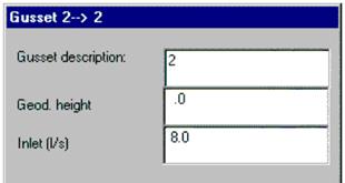
A pipe network may have one or more points of supply. These inlets, e.g. displacement-type pumps with fixed supply quantity, are represented by inlet gussets. In addition to the usual gusset values the inlet gussets contain information about the supply quantity (l/s).
An open run where the outlet quantity results from the existing pressure profile can be represented by a free outlet. Masks for free outlets contain additional information about the counterpressure. An outlet into the free atmosphere is indicated with a ‘0’.
In the masks "Supply" to "Free outlet" the input of the geodesic height is dropped for gas flows.
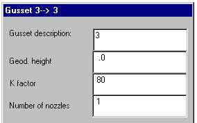
The sprinkler nozzles are characterized by the K factor, i.e. the water quantity in l/min a nozzle is spraying at a pressure of 1 bar before the nozzle. At one gusset several nozzles can be considered.
For gas flows the input of the specific gas constant is expected. Input of the compressibility factor is optional.

Start the calculation with this button.
Further comments are provided in the section "Arithmetical accuracy" see page 20 ("Options" menu).