Creating a pipe network
The medium is selected on the top left of the basic mask. The default setting is Liquid (incompressible medium).
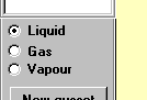
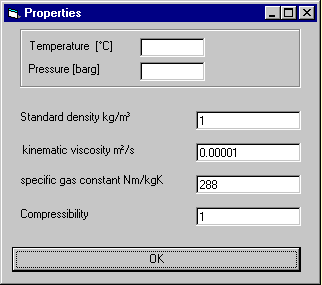
By clicking on Gas the input mask for the specification of the physical data is displayed. Overwrite the relevant fields with the current input values and click on OK.
If vapour has been selected an extended input mask with a water table button is displayed.
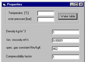
After entering the temperature and the pressure and clicking the button "Water table" the values for steam are entered in the lower fields (see following figure).
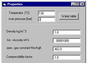
If there is no steam for the entered values of pressure and temperature a corresponding message appears: "Attention flow is liquid".
Example: pressure > 1 bar, temperature < 100 °C.

Example for liquid flow in case of steam. The program Rohrnetz (pipe network) automatically enters the correct values for the liquid phase.
A pipe is created as a connection of two gussets. For this you have to drag with left mouse key pressed from the centre of one gusset into the area of another gusset. After dropping the left mouse key the following mask for the description of the pipe is displayed:
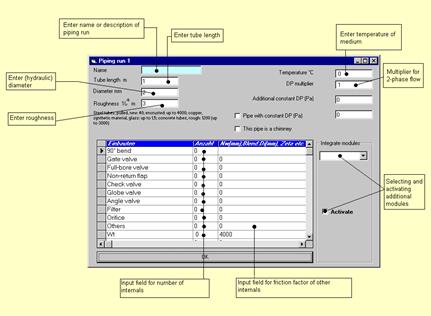
For each run a pipe length, a diameter and the pipe roughness have to be entered. To reduce the number of the required inputs to the minimum, the length, the nominal width and the roughness of the run situated directly before are taken and suggested as input variables. These suggested values can be overwritten if necessary. If internals, such as bends, fittings, orifices etc., are in the run it is possible to enter the number of the different internals into the corresponding input field. For bends the friction factors of 3D-bends are determined automatically by the program. For fittings the friction factors according to the VDI heat atlas / chapter LC are provided. If the fitting has a reduced diameter, this can be entered in the input field at the back. For orifices the orifice diameter and for other internals the friction factor has to be entered in this field.
Entries in this mask can be corrected at any time. Activate the mask for the runs by double-click on the corresponding run. Then the desired values are modified.
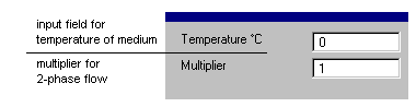
In case of gas flow it is also possible to enter the temperature. If it is a two-phase flow this can be done by the two-phase multiplier according to Lockhart-Martinelli:
Usually, a pipe system has at least one inlet in the form of a supply or pump and at least one outlet. At least one pipe has to be between these gussets.
Note: If a pump has to be used that the Q-H-curve has not yet been defined for, it is recommended to replace the pump gusset by a supply for the time being. In the first calculation step the pressure profile and the mass flows are determined. After that, an appropriate pump with corresponding Q-H-curve can be chosen easily from the pump manufacturers' catalogues and can be put into the system.
Create a high tank and enter the supply pressure.
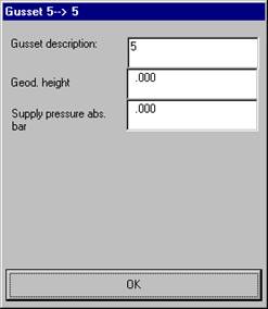
The supply pressure has to be given as an absolute value. For an excess pressure of 2 bar enter the value 3 as supply pressure.
The basic mask looks as follows:
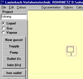
Draw the pipes. You can use the button "New gusset" and integrate this new gusset or just draw a new pipe from the last gusset to the new target.
Note:
A pipe can be drawn from an existing gusset by selecting the gusset centre and drawing the new pipe with pressed left mouse key from there.
Enter the gusset data and pipe data into the corresponding masks.
Add the other gussets and pipes and create an outlet gusset.
Please note that a supply (high tank) and a free outlet do not provide sufficient data for the calculation of the system. Specify further parameters by
integrating a pump or
using a defined outlet.
Start the calculation by clicking the
button  or selecting the menu
item "Calculate" in the "Edit" menu. After the calculation
has been performed the program transfers the results into your graphics.
or selecting the menu
item "Calculate" in the "Edit" menu. After the calculation
has been performed the program transfers the results into your graphics.
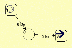
Document the required results or modify your pipe system.
Use the options in the "Results" and "Documentation" menus to display the desired variables.
The character set for the display on the screen can be set in the "Options" menu under "Character font".
The displayed area can be adapted in the menu item "Zoom" in the "Edit" menu.
In general, there are two possibilities to format the printer output:
Select to print only the area displayed on the screen or the entire pipe network. If necessary, change the printer font before printing to improve legibility. Change the size of the representation in "Edit" – "Zoom" to make it easier to select the desired area with "Print" – "View".
The character set for the printer output can be modified in the "Options" menu under "Printer font" to avoid the overlapping of output text and output data. If necessary, print several partial views to improve legibility of the printout.